Li-ion Batteries: How safe are they to use again?
Li-ion cells and modules undergo capacity degradation over time, this article dives deeper into the safety of aged cells and modules and looks at the role cell design can play in the degradation process.
The lithium-ion battery chemistry is used in a myriad of applications today, from portable consumer devices to large automotive and stationary grid energy storage systems. Of the commercially available battery chemistries, the lithium-ion battery is one that has a very high volumetric and gravimetric energy density along with a long cycle and calendar life. This chemistry is also capable of providing power from medium rates to very high rates. Several cathode and anode chemistry combinations can be used in the build-up of lithium-ion cells and several design configurations can be used to build batteries with this chemistry.
Cycle life and calendar life of lithium-ion cells and batteries are highly dependent on several factors, namely, the charge and discharge rate, the environmental temperature, the temperature gradient within the battery design, the voltage range for charge and discharge, the number of cycles and the quality of the cells that go into manufacturing the battery. In addition to this, the voltage at which the cells and batteries are stored in between usage or under long-term conditions will affect both the cycle and calendar life. The aging of lithium-ion cells and batteries is manifested as capacity loss and deviation of cell-to-cell open-circuit voltage, capacity, and internal resistance. The components of the cell experience a wide range of degradation and this is manifested as morphology changes in both electrodes, cracking and delamination of the electrodes causing loss of active material and electrical isolation as well as changes in intercalation kinetics. Within the anode, active lithium loss due to its trapping internal to the electrode is observed, and with respect to the cathode, destabilization and structural disorder, disproportionation, and metal dissolution are observed. The electrolyte undergoes decomposition, has side reactions with the solid electrolyte interphase (SEI) and the binder, causing the production of hydrogen fluoride (HF) as one of the by-products that can be in the gaseous form that leads to swelling that is easily observed in pouch format cells but not in metal can cells. Lastly, corrosion of the metal current collectors and pouch in poorly designed pouch formats have also been observed with age.
High-quality lithium-ion cells, especially those made exclusively for a particular high-value application such as electric vehicles can be quite expensive. These applications not only require a battery but also the entire system that goes along with it in order for it to operate safely. Lithium-ion batteries used in electric vehicles, whether hybrid, plug-in, or pure electric, are used only for a certain period to ensure that vehicle performance targets are met. It is traditionally acceptable to remove a battery from service after 20 percent of the battery capacity is depleted. However, with lithium-ion batteries, even after 20 percent is lost, there is still a remarkable performance that is observed. Hence, in the past few years, batteries used in automotive applications have been repurposed for use in stationary grid energy storage applications.
This can be done by breaking down the larger batteries into modules or down to single cells that can be reconfigured for the next application.
The intent of the collaborative work carried out by Underwriters Laboratories and Purdue University was to understand and characterize the safety trends with respect to varying levels of capacity loss in lithium-ion cells and modules. This type of data is not widely found in the literature and the need to understand safety of aged cells and modules seemed of vital importance. The authors have presented the data in this article at several conferences as the work progressed and published the cycle life aging study.
The work carried out included cycle life testing of 3.35 Ah cylindrical (18650) and 3.3 Ah pouch format lithium-ion cells and modules. The cylindrical cells and modules were cycled under two different voltage ranges, namely, the manufacturer recommended voltage range of 2.7 V to 4.2 V and a reduced voltage range of 2.9 V to 4.0 V. The cylindrical cells were removed at 10 percent, 15 percent, and 20 percent capacity loss and tested under overcharge conditions and external short tests and compared to that obtained for fresh cells under the same off-nominal conditions. The pouch format cells were cycled under the voltage range recommended by the manufacturer and cells were removed at different capacity loss levels between 15 and 20 percent in addition to the 10 percent, 15 percent, and 20 percent capacity loss and subjected to overcharge and external short tests and compared to the results obtained with the fresh cells.
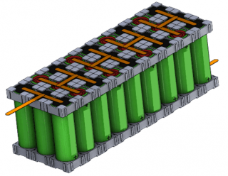
In addition to the aforementioned tests, an electric vehicle drive cycle profile was used to test single cylindrical cells at three different temperatures of 10 °C, 25 °C, and 40 °C. The cells subjected to the drive cycle protocol were tested for safety after more than 20 percent capacity loss was observed. The cylindrical cells were also configured into 3P9S modules and the pouch format cells were configured into 5P5S modules (Figure 1). The cylindrical cells modules were cycled under the two equivalent voltage ranges similar to the cells, that is, under the manufacturer recommended voltage range and the reduced voltage range.
The pouch format cell modules were cycled only under the manufacturer recommended voltage range. The fresh and cycled cylindrical cell modules were subjected to overcharge tests. The fresh and cycled pouch format cell modules were subjected to overcharge and external short circuit tests. All off-nominal tests were carried out on fresh and aged cells at 100 percent state-of-charge (SOC). The cylindrical cells were subjected to an overcharge current of 1C rate for 6-hours while the pouch format cells were subjected to different charge currents as indicated in the section below detailing the results of the pouch cell tests. Cells from each capacity loss group were also destructively analyzed and the electrodes studied using Scanning Electron Microscopy (SEM) and Energy Dispersive Spectroscopy (EDS) analysis tools.
Figure 1. Schematic of 3P9S Cylindrical module (left) and 5P5S pouch format cell module.
Cylindrical Cell Results:
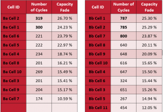
It was observed with the cycle life testing to 20 percent capacity loss that cells cycled under reduced voltage range provided more than twice the number of cycles compared to the cells cycled under manufacturer recommended full voltage range, although the capacity obtained in the beginning of the cycle life test was less for the reduced voltage range cells (Table 1).
Table 1. Number of Cycles for cells cycled under the manufacturer recommended voltage range of 2.7 to 4.2 V (Left) and under the reduced voltage range of 2.9 to 4.0 V (Right).
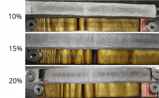
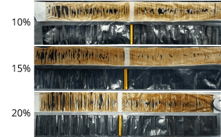
The degradation observed in the electrodes and the separator of the cells cycled under the manufacturer's recommended voltage range to different levels of capacity loss is shown in Figure 2.
Figure 2. Anode (left) and cathode (right) electrodes with separators after cycling to various levels of capacity loss, as indicated, under the manufacturer's recommended voltage range.
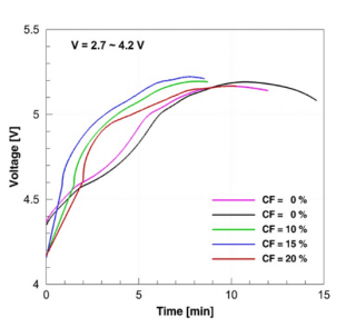
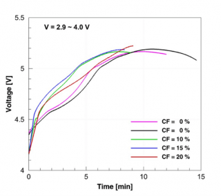
The overcharge tests on the fresh and cycled cells showed that the cycled cells experienced current interrupt device (CID) activation much earlier when compared to the fresh cells (Figure 3). The activation of the CID causes the two discs of the CID to separate thus causing an electrical disconnect in the positive terminal of the cell rendering the cell inactive. The change in voltage during the overcharge test is shown in the figure and the activation of the CID is signified by the point at which the cell voltage is lost due to CID activation. The earlier CID activation might be due to the accumulation of gases during the cycle life aging process since the CID activation occurs due to the pressure increase inside the cell caused by gas production above a certain voltage.
Figure 3. Plot showing CID activation times indicated by the end voltage readings for the overcharge test using a 1 C current on fresh and cycled cells at 100 percent SOC, cycled under the two different voltage ranges.
Cells with different capacity loss levels subjected to external short tests did not show any specific trends with respect to temperature or voltage. The cells used in the test were equipped internally with Positive Temperature Coefficient (PTC) device to protect against surge current. Even with the activation of the PTC, the cell temperature reached an average of 65oC for about 3-hours until the cells were completely discharged.
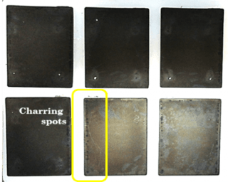
Destructive analysis of the cycled cells subjected to overcharge and external short circuit tests indicated that despite the activation of the internal protective devices, heat damage was observed on the electrodes and separator (Figure 4). The heat damage resulted in the ceramic coating on the separator being stuck to the cathode and active material from the cathode being stuck to the separator.
Figure 4. DPA showing cathode and separator of cells at 100% SOC with 20% capacity fade subjected to (left) external short circuit test and (right) overcharge test.
At the module level, the fresh module exhibited full fire and thermal runaway under an overcharge condition despite the internal CID protective devices present in the cells. However, the aged modules with 20 percent capacity fade did not undergo fire or thermal runaway. This may be due to early CID activation due to the accumulation of gases during the cycle life of the cell as well as due to the decreased energy in the aged module.
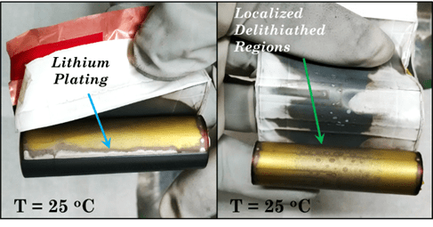
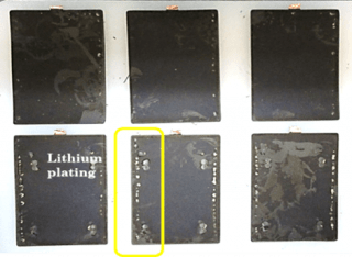
Cells tested using the electric vehicle drive cycle profile showed that at about 20 percent capacity fade, about 13 weeks of performance was obtained at 10°C, 29 weeks of performance was obtained at 25°C and about 24 weeks of performance was obtained at 40°C. Destructive analysis showed that the middle (1/3rd the length) of the anode electrode lacked lithium intercalation (Figure 5).The aged cells were subjected to external short and overcharge tests and destructive analysis of the electrodes and destructive analysis showed lithium plating in addition to the areas that lacked lithium intercalation.
Figure 5. Anode electrodes showing lack of lithiation (labeled delithiated areas) in more than 1/3rd area and lithium plating after 20 percent capacity fade for cells tested using the electric vehicle drive cycle at different environmental temperatures.
Pouch Format Cell Results
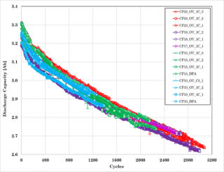
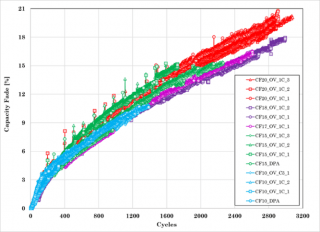
Cycle life testing on the pouch format cells indicated that the number of cycles obtained for the various levels of capacity loss far exceeded those obtained for the cylindrical cells (Figure 6). The degradation observed on the electrodes are shown in Figure 7 for the cell that had 20% capacity loss.
Figure 6. Cycle life capacity trend and capacity fade plots for the single pouch format lithium-ion cells.
Figure 7. Ageing effects on anode (left) and cathode (right) after 20 percent capacity loss for the pouch format cells.
Overcharge of fresh cells was carried out using various currents and it was found that the cells experienced fire and thermal runaway at 1C and 0.5C rates whereas they did not experience thermal runaway or fire at 0.3C rate (Figure 8) but displayed swelling. Hence 0.3C rate was used as a baseline for comparison with the cells that underwent the cycle life tests to various levels of capacity loss.
Figure 8. Overcharge of fresh pouch format cells (left) at 1C rate current and (right) at 0.3C rate current.
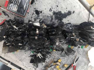
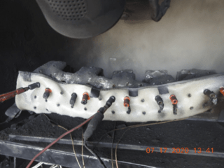
Overcharge using 0.3C current of the fresh and aged modules with 20 percent capacity fade resulted in complete thermal runaway and fire (Figure 9) confirming that cell level tolerance (Figure 8 right) does not necessarily translate to module or battery level tolerance.
Figure 9. Photos of overcharged fresh (left) and aged to 20 percent capacity fade (right) modules.
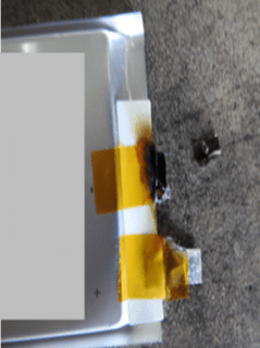
External short circuit tests on fresh cells resulted in the negative tab burning off and the maximum temperature experienced by the cells was about 75°C. (Figure 10). The fresh module underwent full thermal runaway with a fire under an external short test and only the tabs burned off in the aged module with 20 percent capacity fade.
Figure 10. External short test on pouch format lithium-ion cell showing burnt tab (left) and voltage and temperature plot (right).
Summary:
Lithium-ion cells and modules undergo capacity degradation at different rates depending on several factors. The cell design which includes the internal construction and the amount of electrolyte as well as the rate capability of the cells play an important role in the degradation. It was observed with the cylindrical cells that in spite of the internal protective features activating under off-nominal conditions of overcharge and external short circuit, heat is produced internally and hence changes to the electrodes and separator are observed in both the fresh and the aged cells. Cylindrical cells and modules aged to 20 percent or higher capacity fade are more benign than the fresh cells under the off-nominal conditions tested. The pouch format cells are still reactive at 20 percent capacity fade under the overcharge conditions but experience tab burning under the external short conditions. Lack of tolerance of cell modules to off-nominal conditions that the single cells had tolerance too is observed.
Due to the changes that occur to the cell components that include the electrodes and the separator, it is imperative to carry out extensive testing on the used modules before they are placed in the second-use application. It is recommended that representative cells and modules be studied to characterize their nominal performance required in the new application as well as subject them to the off-nominal conditions to confirm that the safety controls are designed correctly for the second application. It is also critical that the history of the cells and modules in the first application be reviewed thoroughly to understand the health of these before they are placed in the new application. Lastly, once configured into the battery system for the second-use application, certain parameters such as the voltage, current and temperature should be monitored well and excursions outside the limits set should be reviewed carefully. A periodic health check and maintenance check should be performed on the battery system to confirm its health and safety in the new application.
The UL 1974 outlines the methodology to characterize the health of the cells and modules that go into a second application and includes characteristics that need to be checked closely in the second application.
Authors:
Judith Jeevarajan, Ph.D., Research Director, Underwriters Laboratories
Daniel Juarez Robles, Ph.D., Research Scientist, Underwriters Laboratories
Tapesh Joshi, Ph.D., Research Scientist, Underwriters Laboratories
Kanarindhana Kathirvel, Senior Project Specialist, Underwriters Laboratories
Saad Azam, Graduate Student (UL employee when tests were conducted), Dalhousie University
Partha Mukherjee, Ph.D., Associate Professor, Purdue University
The authors would like to acknowledge Prof. Partha Mukherjee's team at Purdue University, Dereck Lenoir and his test team at the Energy Systems Test Area (ESTA) in NASA – Johnson Space Center and Dr. Bapi Surampudi and his team at Southwest Research Institute (SWRI) for collaborating and carrying out the tests with the Battery Safety team at Underwriters Laboratories. The authors would also like to acknowledge that this work was carried out with Underwriters Laboratories internal research funds. More information about these studies can be obtained by contacting


